• Blog
  • Wastewater Testing
  • Bioaugmentation Applications
  • Useful Information
  • About Us
BIOLOGICAL WASTE TREATMENT EXPERT
Contact Us

Wastewater septicity & redox potential - how they relate

9/29/2015

 
Picture
We often use the word septicity to describe wastewater with malodors from hydrogen sulfide and dark color from the reaction of iron with sulfide (FeS). As with most things wastewater, it is a more complex condition than can be described by hydrogen sulfide or color.

Septic wastewater forms when you have:
  • Soluble organics in abundance (BOD5)
  • Absence of dissolved oxygen (what was there is depleted)
  • Lack of alternative electron acceptors (in this case usually NO3, NO2, Fe(III))
  • Microbes with anaerobic metabolic pathways (usually in abundance in sewage)
Steps in Conversion of Raw Wastewater to Septic Wastewater
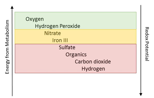
  • Dissolved oxygen becomes depleted (Redox potential falls below 0 mv @ 7 pH)
  • Soluble BOD continues to fuel microbial growth
  • Nitrate/nitrite/Fe is used by microbes (Redox continues to fall below -150 mv @ 7 pH)
  • Sulfate and sulfur are used by Sulfur reducing bacteria (SRB) as an electron acceptor for organic degradation. (Redox falls into the - 200 mv @ 7.0 pH)
  • Non SRB bacteria use organics as the electron acceptor which creates organic acids and hydrogen. Some including propionic, butyric, and acetic have strong odor potential.
  • In collection systems, we rarely drop below - 450mv redox where we would start to see methane production.
At the redox potential below -200mv we are getting an accumulation of reduced sulfur compounds (H2S, S=), mercaptans, volatile organic acids, and other malodorous metabolites.

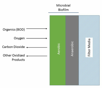
When this water hits an aerobic treatment system the following happens:
  • Highly soluble organic acids and reduced compounds create a biochemical and chemical oxygen demand that depresses D.O. and favor the growth of microbes that grow well on highly soluble organics @ low DO (i.e. filaments)
  • Sulfide and many organo-sulfide compounds are toxic to autotrophic nitrifiers that are needed for ammonia removal
  • Once aerated or redox is increased back to positive range, the waster is back to "normal".


Best practices for lift station grease both cleaning & control

9/23/2015

 
PictureExample grease trap that causes problem with lift stations.
Lift stations serving high density restaurant and other institutional development tend to have a "perfect storm" for building solid grease on station walls and equipment. In addition to the problems with grease fouling equipment, the anaerobic layer under the grease produces corrosion and odors from hydrogen sulfide and volatile organic acids/mercaptans. Today, I want to discuss best practices for cleaning the lift station once it has heavy accumulation and how to prevent the extensive grease buildup following cleaning.

As with anything wastewater, the first option should be to keep grease out of the sewer lines. To accomplish this, the inspectors need to check for proper grease trap installation and maintenance from upstream restaurants and kitchens. What is proper maintenance? The biggest thing is to get managers and employees to understand the grease trap's importance and function. Once they understand the purpose and how the grease trap is often the source of mystery odors in the parking lot area, people tend to check to ensure proper operation and pumping frequency. Some municipalities ban all grease trap additives - based on data we have collected on BOD, FOG, COD - combining a high quality microbial culture with good maintenance practices will result in less grease going to the collection system and lower pumping costs for the restaurant. The cultures work by initiating biodegradation of grease into short-chain fatty acids - via the beta oxidation process. A biologically treated grease trap (no mixing or aeration) should have no solid grease cap but instead have a clear water with the appearance of fluffy light color grease (actually fatty acids) to indicate the need for pumping.

Even with trap maintenance, long retention time stations can still experience grease buildup from residential and restaurant sources. As soaps and surfactant bound grease sits, the pure grease and long chain fatty acids will start to "break out" and accumulate on surfaces. To clean the lift station with heavy grease accumulation - the last option should be d-limonene or solvent treatment. Why you may ask? Well using a solvent to remove grease buildup releases a slug of grease and fatty acids to the treatment plant downstream. In addition, I have seen heavy use of d-limonene causing severe biological upset at the wastewater treatment plant as high concentrations of many natural plant soaps/oils are toxic to many bacteria.

What should be done? First - clean using pressure washers and an number of non-solvent based cleaners. The downstream treatment plant should be notified of the activity to prepare for higher FOG loading. The idea is to break off the most problematic grease  on equipment and floats to prepare for the next step. Instead of using strong chemicals and mechanical cleaning, the lift station can be often maintained using biological treatment. To prevent both odors and grease in lift stations, we have used combinations of aeration and microbe addition. For hydrogen sulfide (H2S) and grease control, I recommend first evaluating an microbe addition. They can be added via manual dose, metering pump, or in solid block form. I have had best results with most control options with metering pump option. If odors are still a problem from H2S coming from feed lines, the addition of aeration or upstream nitrate addition my be needed. Aeration using atmospheric oxygen is usually the lowest cost option over pure oxygen, hydrogen peroxide, or nitrate.

As with grease trap additives, a high quality lift-station microbial product will contain organisms capable of beta-oxidiation of long chain fatty acids. In some heavy FOG lift stations, it may be necessary to add a small amount of surfactant with the cultures to encourage biological activity We do this same process in soil remediation to improve bacteria access to insoluble fatty acids. What happens in the lift station is the bacteria start the biological degradation process that will be finished downstream in the aerobic and anaerobic biological treatment units. By converting a long chain, insoluble fatty acid to shorter chain fatty acids, the "grease" will not solidify and becomes more amenable to degradation by organisms without extensive beta oxidation metabolic capabilities.


What should I do if a large grease or oil spill hits my biological treatment unit?

9/21/2015

 
Picture
Grease and Nocardia foam on oxidation ditch. (http://web.deu.edu.tr)
No matter how careful you operate the collection and pretreatment systems, the biological unit sometimes receives spills or shock-loads. Today, I am going into one of the most common spills - grease or oil (let's use FOG from now on for grease). What makes FOG so difficult is:
  • Insoluble nature makes it difficult for bacteria compared to soluble organics.
  • Takes time to degrade!
  • Causes foaming on aeration basins
  • Contributes to floating sludge on secondary clarifiers
  • MLSS has oil droplets and excess water which makes for messy dewatering
  • Fixed Film or mobilized beds can become coated with FOG - which can foul the media by "smothering" the biofilm
  • Long term high FOG can encourage problem microbes such as Nocardia (causes thick greasy foam)
In this case, we will discuss response actions to a one time high FOG release into the system. In most cases we do the following:
  1. Get ready to add anti-foam & secondary clarifier polymers.
  2. Increase wasting rates to get rid of FOG saturated MLSS.
  3. Try to maintain a Dissolved Oxygen (DO) above 2.0 mg/L to maximize biological activity.
  4. Check upstream to find cause of FOG and try to make prevent further introduction of FOG.
  5. With high wasting rates, it is a good idea to add bioaugmentation cultures to increase the number of active degrading microbes in the mixed liquor.
  6. In fixed film systems adding bioaugmentation cultures can help re-establish the biofilm that was damaged by the FOG. It may be necessary to actually clean some of the media with surfactants if there is heavy grease buildup.

Adding fixed film (IFFR) to an activated sludge system to improve performance

9/13/2015

 
Picture
Many companies are manufacturing synthetic packing materials for retrofit in existing activated sludge systems. The packing may be suspended within the mixed liquor or fixed in the aeration basin In either form, the addition of fixed film support allows for a greater biomass concentration in the biological unit which allows for higher waste treatment loadings with the same size basin by keeping consistent F/M and solids flux in the secondary clarifiers within design operating range.

As with all fixed film systems, the basis for performance is the establishment of a stable biofilm on the carrier. As with the trickling filter, the biofilm works in the same manner.

One of earliest retrofit suspended growth systems utilized polyurethane foam pads with a bulk density of 0.95 (or slightly lower than water). Adding the pads at 20 - 30 by basin volume with screens to keep the pads in the aeration basin, results in an equivalent MLSS concentration of 5,000 - 9,000 mg/L. Note that this system maintains the biomass recycle from the secondary clarifier.

Another retrofit, is the moving-bed biofilm reactor modification where the aeration basin is filled with 25 - 5i0% tank volume of  polyethylene solid carrier media. The media and associated biofilm are suspended by aeration and maintained in the tank by a screen leading to the clarifier. What is good about the MBBR system retrofit, is the secondary clarifier does not recycle biosolids to the aeration basin - the clarifier only settles sloughed solids. Both oxygen and mixing are provided by coarse bubble difffusers that have much fewer problems with fouling when compared to fine bubble diffusers. Additional sections can be used for denitrification by replacing aeration with mechanical mixers to provide for media under anoxic/anaerobic conditions needed for nitrate/nitrite removal to nitrogen gas.

Steady-state vs upset conditions in wastewater systems

9/7/2015

 
When a biological wastewater system is running a near full efficiency, it is said to be in steady-state. While this is actually this is a zone between stationary and decline phase growth depending upon the system, the goal is to remain in a set point with respect to biological reproduction, cell lysis, and biopolymer production that maintains desired effluent quality.

Where is this point on the biological growth curve?

Picture
Note that most conventional activated sludge systems as seen in municipal wastewater treatment are designed to run in the stationary growth phase. If solids are not wasted which increases MLVSS and lowers F/M ratios, the aeration system and secondary clarifiers can become over loaded with associated problems. The wasted solids from the secondary clarifier still have substantial insoluble organics entrapped in the floc biofilm. The insoluble organics are then degraded in the digester – either anaerobic or aerobic system which by rule operates in decline phase

Most industrial systems are designed to operate at the end of stationary to full decline phase growth. This section has the lowest F/M ratios and in theory most of the insoluble/recalcitrant organics are degraded by the microbes into their component soluble fractions.

What can cause a shift from target steady-state?
  • Rapid increase (or decrease) in influent soluble organic concentrations (BOD5)
  • Hydraulic washout or secondary clarifier problems reduce aeration tank MLVSS
  • Shock loadings - a spill of an insouble organic (ex. grease, oils)
  • Toxic or quasi-toxic influent (ex. cyanide, phenol, solvents) ~ usually seen in industrial wastewater
  • Environmental changes such as pH, temperature, dissolved oxygen, alkalinity especially if change is rapid

Rotating Biological Contact (RBC) - fixed film systems

9/1/2015

 
PictureStandard RBC
Rotating Biological Contact (RBC) treatment systems were developed concurrently with new plastic trickling filter media in the 1960s. An RBC system consists of a series of polystyrene or polyvinyl chloride discs that are partially submerged in wastewater and rotated on a horizontal shaft. As with all fixed film system, RBC units are loaded based upon kg substrate per square meter of surface area.  


Early RBC systems had problems with structural failure (mainly shafts). However most of these problems have been addressed and modern RBC systems do not have these problems. Most installations have multiple RBCs in stages that treat soluble BOD before going to separate nutrient removal sections.


Often we see RBCs used in conjunction with a conventional suspended growth system. The RBC can serve as a roughing filter to reduce soluble BOD prior to the suspended growth system. Most commonly, we have an RBC after the suspended growth system to remove ammonia via biological ammonia oxidation (nitrification) where a fixed film system has greater stability than a suspended biological process.

Advantages
  • Lower energy use than suspended growth systems
  • Stable operation even with hydraulic and organic load variation
  • Low biological solids production
  • Sloughed solids tend to settle readily in secondary clarifier without polymer addition
  • Simple to operate with little daily operator activity required
  • Sludge return is not required (biomass remains as film on discs) – some systems require recycle by design
  • Smaller foot print than suspended growth systems

Disadvantages
  • Must be enclosed to maintain ideal temperatures during cold months
  • Media and shafts are more specialized than most common wastewater equipment
  • As with all fixed film systems the media can be fouled by oils and grease in a spill event
  • Toxic or quasi toxic shocks can make maintaining a biofilm difficult. This can be addressed with response with bioaugmentation cultures (bugs) or adding a biomass recycle from the clarifiers


    Author

    Erik Rumbaugh has been involved in biological waste treatment for over 20 years. He has worked with industrial and municipal wastewater  facilities to ensure optimal performance of their treatment systems. He is a founder of Aster Bio (www.asterbio.com) specializing in biological waste treatment.

    View my profile on LinkedIn

    RSS Feed

    Click to set custom HTML

    Archives

    December 2022
    November 2022
    October 2022
    September 2022
    August 2022
    June 2022
    May 2022
    March 2022
    February 2022
    January 2022
    November 2021
    October 2021
    September 2021
    August 2021
    June 2021
    April 2021
    March 2021
    February 2021
    December 2020
    November 2020
    October 2020
    September 2020
    August 2020
    July 2020
    June 2020
    May 2020
    April 2020
    March 2020
    February 2020
    January 2020
    December 2019
    November 2019
    October 2019
    September 2019
    August 2019
    July 2019
    June 2019
    May 2019
    April 2019
    March 2019
    February 2019
    January 2019
    December 2018
    November 2018
    October 2018
    September 2018
    August 2018
    July 2018
    June 2018
    May 2018
    April 2018
    March 2018
    February 2018
    January 2018
    December 2017
    November 2017
    October 2017
    September 2017
    August 2017
    July 2017
    June 2017
    May 2017
    April 2017
    March 2017
    February 2017
    January 2017
    December 2016
    November 2016
    October 2016
    September 2016
    August 2016
    July 2016
    June 2016
    May 2016
    April 2016
    March 2016
    February 2016
    January 2016
    December 2015
    November 2015
    October 2015
    September 2015
    August 2015
    July 2015
    June 2015
    May 2015
    April 2015
    March 2015
    February 2015
    January 2015
    December 2014
    November 2014
    October 2014
    September 2014
    August 2014
    July 2014
    June 2014
    May 2014
    April 2014
    March 2014
    February 2014

Proudly powered by Weebly
Photos used under Creative Commons from Picturepest, marcoverch, perzonseowebbyra, Picturepest, Picturepest, dsearls, dungodung, Massachusetts Office of Travel & Tourism, aqua.mech, vastateparksstaff, hile, Aaron Volkening, amishsteve, Neil DeMaster, mklwong88, KOMUnews, Picturepest, kaibara87